7" Touch Screen PA-Controller
Calibration:
DSP-7 works with any power / SWR measurement coupler that provides a voltage linear to
the measured power in dBm. The most commonly used chip is the Analog Devices AD8307.
The output voltage of this chip must be set (by a voltage divider) to a maximum value of
2.4 volts. Then it can be used together with the DSP-7 controller. Besides ready-made
couplers or kits like this one, also self-made couplers can be easily adapted to the DSP-7.
In the following this adaptation is described.
Calibration is performed at two power levels. The best accuracy is achieved when one power level is
as low as possible (min) and the other is as high as possible (max).
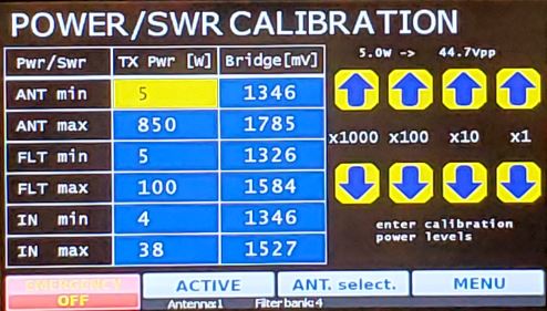
Tap CALIB to open the calibration menu.
The DSP-7 can handle three power / SWR measurement couplers simultaneously. Therefore, the display provides three settings for each of these couplers.
Overview:
Calibration is a very simple operation and can be done in a few minutes:
The calibration in detail:
! Connect a good 50 Ohm dummy load for calibration!
We have to tell the DSP-7 controller what voltage is generated by the coupler at two different power levels. Then the controller can calculate all other values automatically.
For calibration, we need to enter the transmit power (in watts) and the voltage (in mV) generated by
our coupler. We do this for the minimum possible power and for the maximum possible power.
How to reliably measure the output power:
Before we can calibrate, we need to know the actual output power as accurately as possible. A normal
power meter can be used, but these meters usually have an accuracy of only 10% or 20%. A much
better way is to connect a 50 ohm dummy load and an oscilloscope in parallel. Then turn on the
transmitter (FM mode) and measure the peak-to-peak voltage on the oscilloscope. The output power
is: P = Upp² / 400
Example: We measure a peak-to-peak voltage of 200 volts at the dummy load.
The power is then 200
* 200/400 = 100 watts.
Another option is to use a spectrum analyzer in conjunction of and RF sampler to measure an attenuated fraction (e.g. -50dB) of the power going into the dummy load and then convert from dBm to Watt
Example: Calibrate the DSP-7 and the Power / SWR bridge connected to the antenna
output of the amplifier:

Now you can do the same procedure for the other two couplers.
When everything is completed, press the MENUE button to finish. The values will be saved.
Optimize the precision of power and SWR measurements:
DSP-7 with AD8307 based couplers are very precise and work in a completely different league than
conventional power meters.
To achieve the best possible precision, we need to think about 2 points: