7" Touch Screen PA-Controller
User manual Frimware 2.4
When DSP-7 is turned on, a welcome screen appears and all functions are turned off and
disabled (except fan control if the cooler is already hot). If a power relay is used, the
power amplifier supply voltage is also turned off. The only control available is the ON key.
Touching the ON button turns on the PA supply and the controller is in standby mode.
(The photos shown here show DSP-7 in English mode, in the system menu you can switch
to German, everything will then be displayed in German language).
Operating modes
Standby: The power supply is switched on. The transceiver is directly connected to the antenna, the
amplifier is inactive and pressing the PTT has no effect.
Active: The controller is waiting for PTT. When PTT is pressed, the RX / TX relay switches to TX and
the amplifier is in operation.
Emergency-OFF: When the Emergency-OFF button is pressed or an emergency situation occurs, the controller goes into
emergency OFF mode and everything is turned off. Correct the error situation and press ON to
reactivate the system.
When the ON button is pressed after power up, the controller will display the screen with the large
bars.
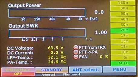
Buttons at the bottom of the screen
EMERGENCY OFF: switches everything off.
ACTIVE: Switches to active mode, the amplifier can be used normally.
STANDBY: switches to standby mode, the amplifier is in standby mode but does not respond to
ANT. select: Manual antenna selection
MENU: Displays the main selection screen
Buttons on the right side
The band select buttons are used to switch to a band. This automatically selects the appropriate low
pass filter and antenna (if an antenna switch is present). The AUTO key can be used if an ICOM
transceiver is connected via the CI / V interface or via RS232 remote control
The assignment of antennas to bands is done in the antenna screen as described below.
The assignment of low-pass filter banks to bands is done in the SYSTEM menu and is described there.
Status line below

Indication of the currently active antenna and selected filter bank.
Screen overview
Press the MENU button to enter the screen selection and system setup
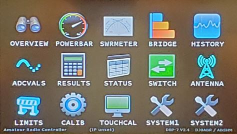
OVERVIEW
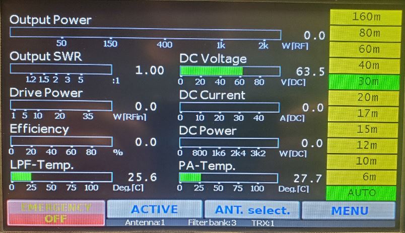
This screen shows the most important operational data.
As with any other screen, the bar shows the average power value and the number shows the
maximum value. The bar has a blue marker which also shows the peak value.
POWERBAR

Larger display of output power and SWR as well as some other measurements
SWRMETER
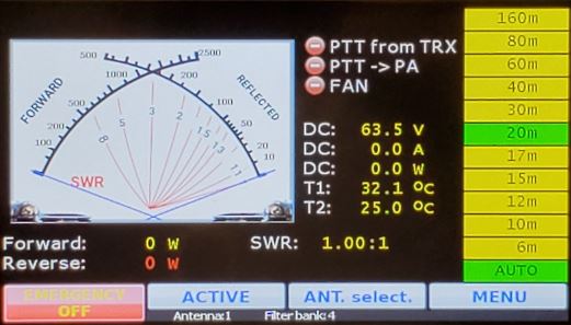
Display of power and SWR in a photorealistic simulation of an analog cross pointer meter as well as some
other measurements
BRIDGE
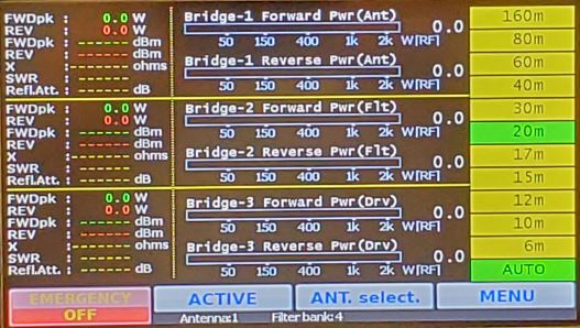
Complete overview of all three power / SWR couplers as well as some calculated values like
reflection loss and others.
HISTORY
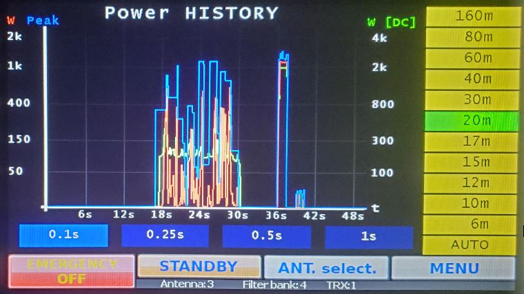
Chart view of output power (red), peak output power (blue) and DC input power (green)
ADCVALS
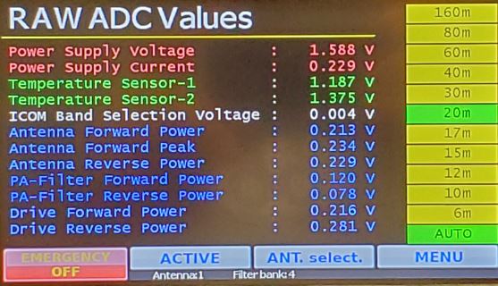
This screen displays the raw values measured by the on-board AD converter. This data is very useful
for installation and debugging purposes.
RESULTS
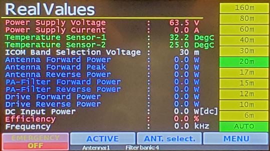
This screen shows the values of the AD converters, but (unlike the previous screen) the real values
are calculated from the raw values.
STATUS
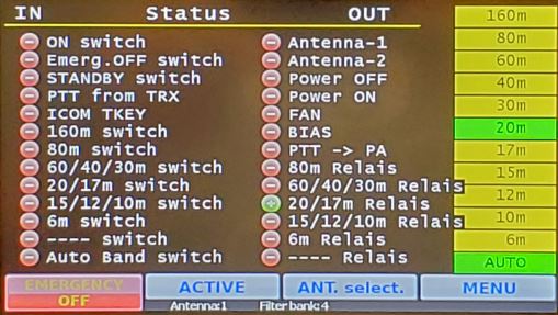
This screen shows the status of the various digital inputs and outputs. It is very useful when setting
up the amplifier. For example, you can see if relays are energized or not
SWITCH
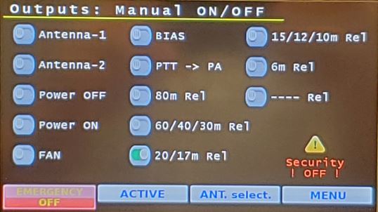
In this screen you can switch the outputs manually. Note: When this screen is open, the automatic
safety functions are disabled. Use this only for testing purposes during setup and maintenance of the
amplifier.
ANTENNA
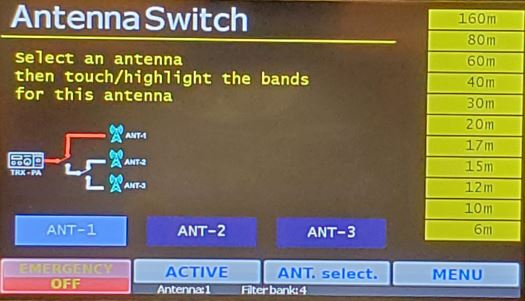
This screen allows you to assign bands to the antennas. The controller has two antenna outputs for
two relays. With these two relays we can connect up to three antennas to the amplifier. The
schematic on the screen shows the state of these relays. Select an antenna ANT-1 to 3 and then
enable or disable the bands for that antenna.
LIMITS
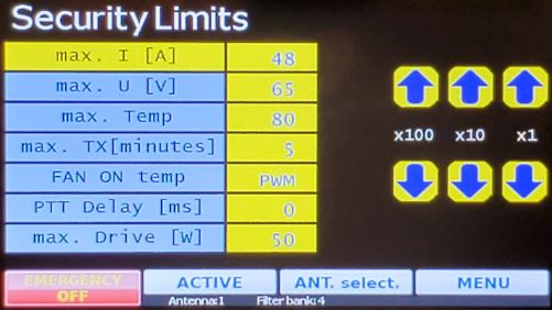
these are the limits of the safety functions:
CALIB
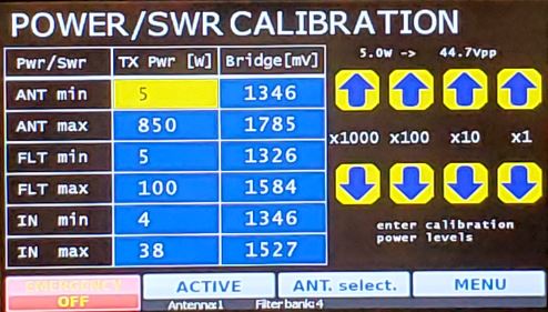
Calibration of the SWR couplers. The calibration procedure is described in a separate topic.
TOUCHCAL
This screen is used to calibrate the touch sensor of the 7“ display. Use a ballpoint pen with the lead
retracted to touch the screen during calibration. This will give much better results than using your
finger.
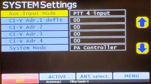
SYSTEM1
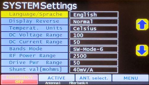
This screen has several system settings:
Assignment of bands to filter banks:
This controller has 6 outputs to switch up to 7 filter banks (Bank-1 is selected when no relay is
activated). Four different band → filter bank configurations are available for shortwave amplifiers.
Select this configuration as follows:
| Filter Relay | SW Mode-1 | SW Mode-2 | SW Mode-3 | SW Mode-4 | SW Mode-5 | SW Mode-6 |
| all OFF | 160m | 160m | 160m | 160m | --- | 160m |
| 1 | 80m | 80m | 80m | 80+60+40m | 160+80m | 80m |
| 2 | 60+40m | 40+30m | 60+40m | 30m | 60+40m | 40+30m |
| 3 | 30+20m | 20+17m | 30m | 20m | 30+20m | 20+17m |
| 4 | 17+15m | 15m | 20+17+15m | 17+15m | 17+15m | 15-10m |
| 5 | 12+12m | 12+10m | 12+10m | 10+12m | 12+10m | 6m |
| 6 | 6m | 6m | 6m | 6m | 6m | --- |
Example: When SW Mode-1 is selected and you switch to the 30m band, relay output 3 is activated.
SYSTEM2
