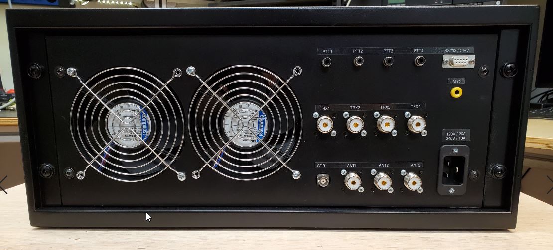
Solid State Linear HF Amplifier
I was looking into HF linear amplifiers and decided to go with a solid state design rather than tuning a tube amplifier every time i change the band.
There are multiple design ideas based on LDMOSFET devices out there. You can find them on various online stores but they are all pretty much identical and based on an NXP application note.
The major benefit of these devices is that you don't need a lot of them in parallel to achieve high power and they run on 50 or 65Vdc which results in a simpler design for a solid state amplifier.
Jim (W6PQL) did a lot of experiments and development work, building various LDMOS amplifiers. Reading through his website is quite educational and highly recommended if you consider building your own solid state amplifier.
Kurt (DJ0ABR) did a great compilation of the best ideas into his design which led to an awesome DIY project that includes a lot of design descriptions and explanations which is also very educational and recommended to read.
His amplifier project can be found here:

Design Decision:
After spending a lot of time researching, reading and watching various Youtube videos i decided to follow Kurt's (DJ0ABR) design with a two LDMOS devices for more ruggedness and increased power.
I also decided to add some additional features:
- SDR monitor output (two HF antennas required)
- Remote control feature to interact with Ham Radio Deluxe for band selection
- PWM cooling fan speed control
- Automatic power limitation via ALC in case of overtemperature conditions
- Soft start for the power supply to reduce inrush current
In addition i reworked all the PCB layouts to use 0805 SMD parts instead of 0603, since i will have to pick and place all the parts by hand.
Control Circuit:
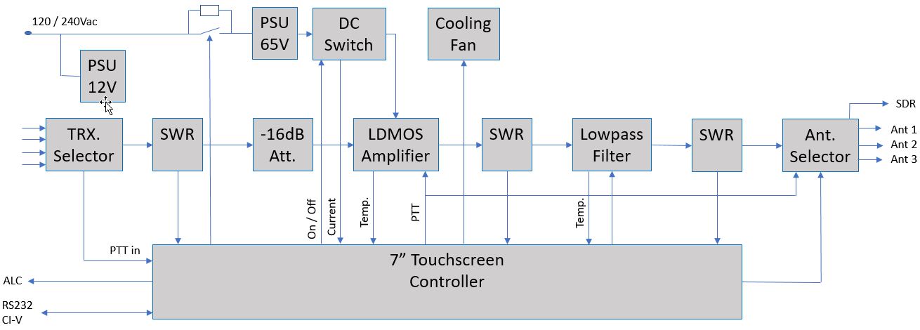
The system includes mutiple safety features to protect the amplifier:
How much Power...... the question everybody is curious about...
When you do your research about solid state LDMOS amplifiers you will find many Youtube videos, showing impressive output
power using a single device.
However, don't let them fool you, since a lot of times, these measurements were taken without a lowpass filter.
While it is true that for example the MRFX1K80H from NXP Semiconductors can generate up to 1800W CW with a single device,
we need to keep in mind that an AB (push-pull) design generates strong uneven harmonics:
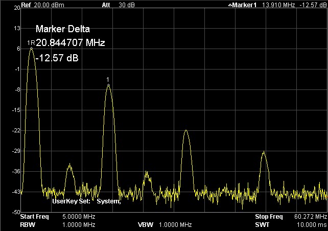
In this example for 40m, the 3rd harmonics is only -12.5 dB below our desired transmit signal.
A power meter ( even high precision ones) will measure the sum of all these harmonics, which is power generated by the amplifier,
but our useful signal is only a portion of it. The lowpass filter is used to suppress the unwanted harmonic signals which will be transformed into heat in the amplifier stage and filter section.
Real Performance:
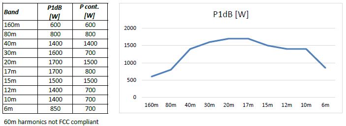
So here now the measurements at the output of the amplifier after the lowpass filter.
Due to stray inductance, capacitance and the transformer material selections, broadband amplifiers like this one have a sweet spot in the frequency band and reduced performance towards the band edges.
On 160m the amplifier doesn't respond very linear on 160m and on 80m there seems to be some sort of resonance that reduces the output power and generates a lot of heat in this filter section. This calls for more research and experiments since the measurements of the filter sections seem to be ok.
However, i am very pleased with the overall performance since i don't have antenna capabilities for 160m and 800W output on 80m is good enough for me.
The cooling system is capable keep the amplifier's temperature in range for continuous CW transmission at the P1dB levels
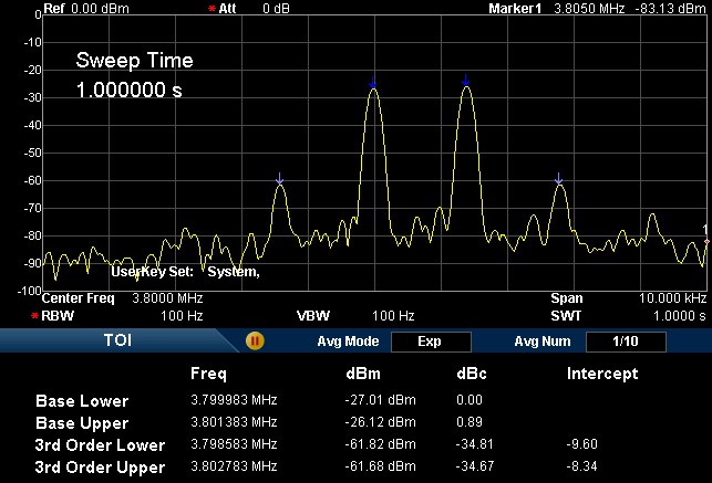
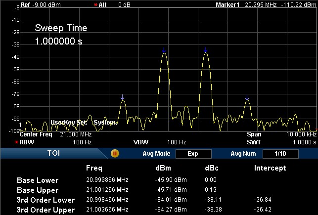
Two-tone third-order intermodulation distortion (IMD3):
The IMD3 measurement shows the distortion products of a nonlinear device by feeding it with two frequencies that are spaced closely. Since our amplifier is not 100% linear, it will create IMD3 products and if they are not suppressed enough they will be noticeable in our transmission or even interfere with adjacent transmissions.
I was trying to find limits or recommendations for acceptable limits. It turns out there is a lot of different opinions but i couldn't find anything solid. However, the Motorola Engineering Bulletin EB38 states that the maximum permissible IMD is not specified, but numbers like -30dB or -35dB are not uncommon.
So don't hold me accountable for the following measurements, but i tried to do my best with the equipment available.
My Kenwwod TS570s without the amplifier shows about -25dBc... so not really great to be used to drive the amplifier for this test. So i had to use my dual signal generator which was not enough to drive the amplifier at high power, but at least the signal was clean.
-34dBc on 80m and -38dBc on 15m seems to be quite acceptable results.