Amplifier Block
I did follow here the design of DJ0ABR as well with the following modifications:
My design considerations
Water cooling would be ideal, but i didn't wanted to run water hoses in my shack and opted for air cooling.
This requires good size heat sink with high airflow to run CW in full power. Since i mostly operate in SSB, this would not be a big problem... even with a legal limit QSO, the fan usually runs only on low speed.
I am using a configuration with two LDMOS devices for the following reasons:
One of the main problems with high power solid state amplifiers is to ensure a low thermal resistance between the
semiconductors and the heatsink in order to remove the generated heat into the heatsink.
The realistic efficiency of the amplifier is between 50% to 75%, depending on the frequency. I did set my bias
current to around 1.7A per device which results in over 200W thermal losses into the heatsink as soon as the PTT is activated, even without any signal being transmitted. When we transmit for example a 800W signal 50% efficiency, we have also 800W losses (heat) inside the amplifier.
Therefore the cooling design is very essential.
Assembly
Kurt made the effort and wrote an construction manual: INSTRUCTIONS
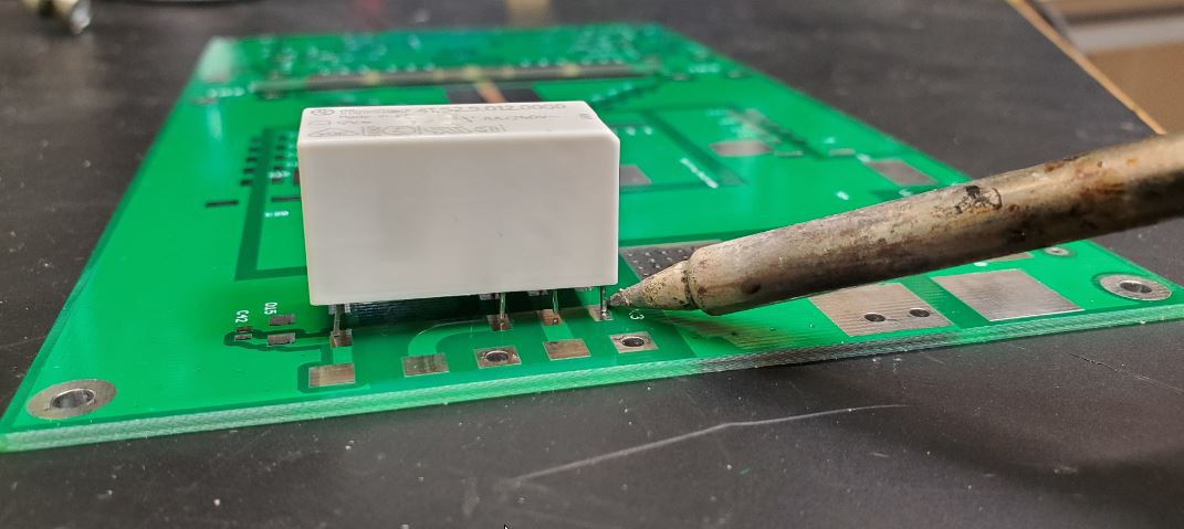
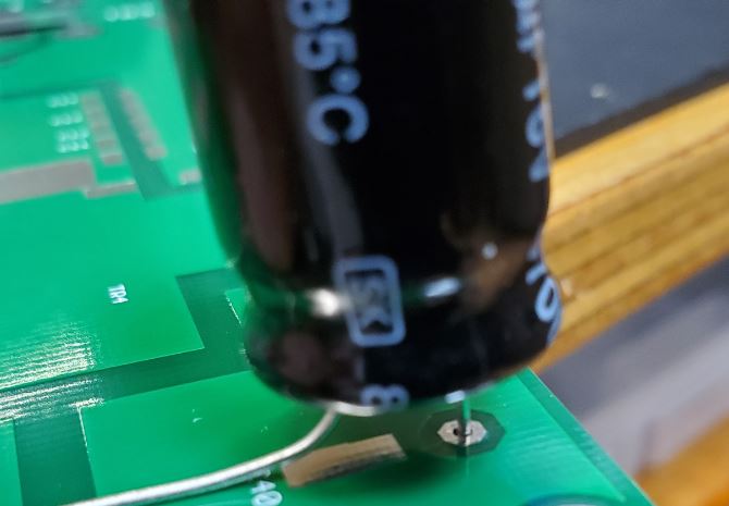
To simplify the the heat spreader and be able to use a single piece of copper, the through hole components like relays and capacitors have to be soldered on top of the circuit board. This is probably not ideal, but works very well.
Don't be greedy with the solder here to ensure good contact with a large surface connection to reduce impedance
Copper heat spreader
As mentioned before a copper heat spreader is needed to ensure a low thermal resistance for the heat transfer.
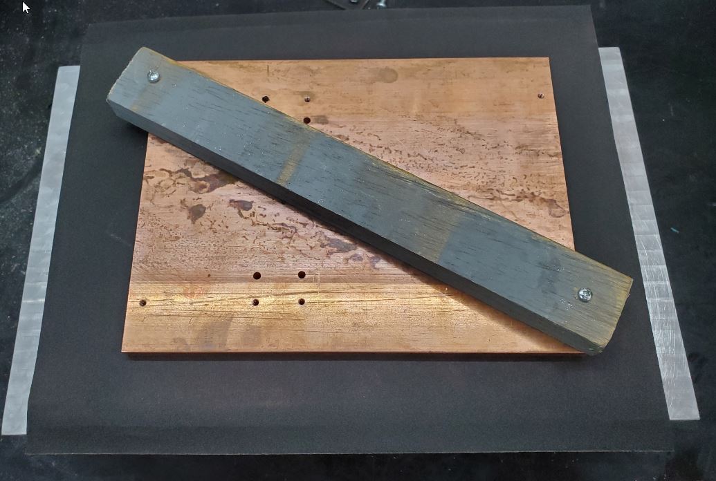
A raw copper bar is not flat enough to achieve this low thermal resistance. Ideally the copper bar and the heatsink
surface should be machined. I was able to get my hands on a machined heatsink and decided to use this surface to
sand and polish the copper bar instead, by using fine grid sand paper between heatsink and copper bar:
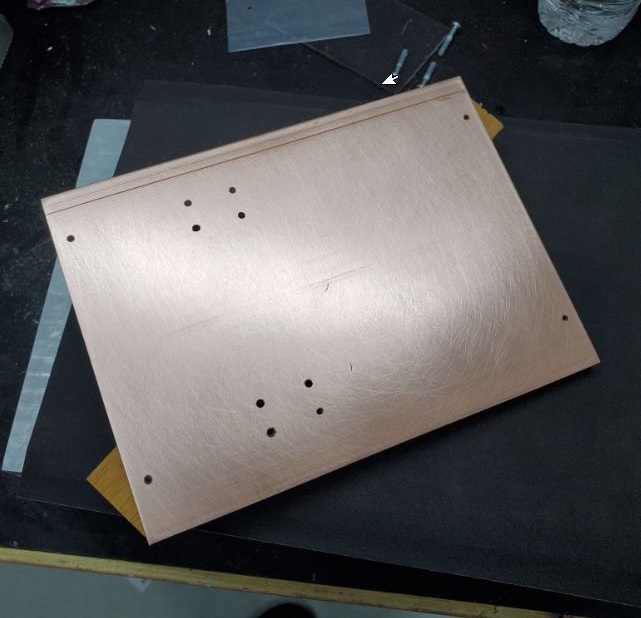
The result:
LDMOSFET installation
To further improve the thermal transfer, the LDMOS devices are soldered onto the copper heat spreader.
Since my heat spreader was not machined and doesn't have a groove i drilled small holes and used some Teflon wire
to hold the devices in place.
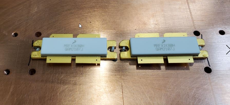
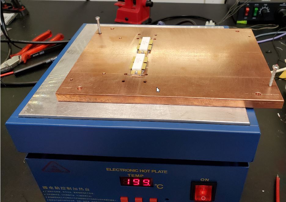
Then i placed solder in a meander form under the devices and used a hot plate to solder.
You can use a Ceran stove burner as well (when your wife is not at home ;-) with a infrared thermometer to
control the temperature
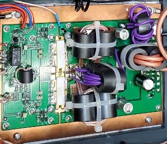
Circuit description
The input schematics : INPUT
The output schematics: OUTPUT
Transmission Line Transformer: TLT
Construction manual: INSTRUCTIONS
PCB data of my modified version
Schematic file
Layout file
Gerber files