1.5kW HF Dummy Load
When i decided that i want to build an HF linear amplifier, it was pretty clear that i would need and decent dummy load for testing.
A quick research in the internet made me realize that high power dummy loads are rather expensive and won't fit my budget.
I also found a solutions using a big jar, filled with salt water, but messing with a lquid and adjusting the salt content wasn't verry appealing to me and an air cooled solution would be my first choice.
Further research revealed some high power HF-resistors that are available on ebay or Alibaba for a decent price around $60 each.
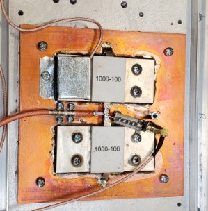
I decided on two 100Ohm / 1000W resistors, connected in parallel.
The next concern was the heat transfer from these resistors into the heatsink. Multiple tests showed that a copper heatspreader besides
a large heatsink is needed.
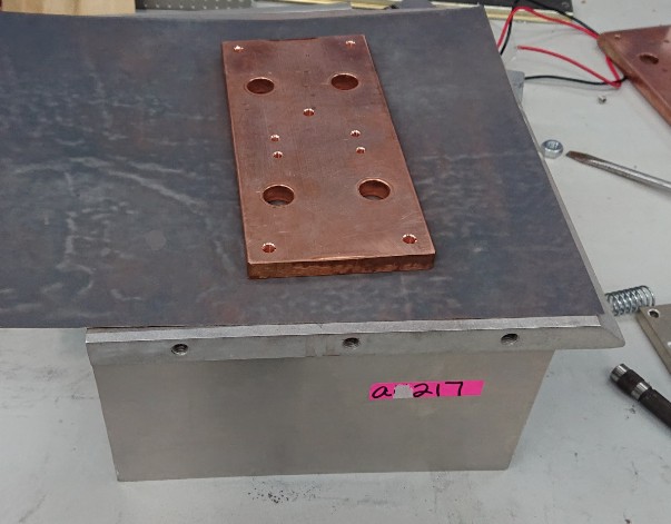
I found a used heatsink (8in x 8in x 4in) and a 6in x 6in x 5/8in copper bar on ebay.
The raw copper bar is far from being flat. In order to get a low thermal resistance between resistors to copper plate and copper plate to heatsink, the copper plate needs to be either machined on a mill or sanded / polished on a flat surface.
I used the heatsink itself... which took a long time to do, but it worked...
The resistors were soldered on the copper heat spreader and the screws tightened while the solder was still fluid.
This picture also shows the temperature sensor (under the metal cap) and the -65dB pickup for the power measurement
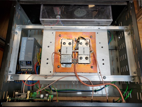
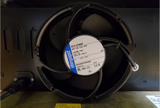
In order to remove the heat, a decent air flow is needed.
I am using a 67W DC fan with PWM speed control and tach signal output. This powerful fan moves up to 418 cfm air
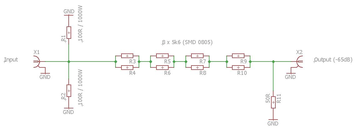
Schematic with -65dB attenuator:
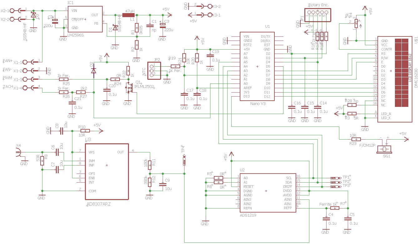
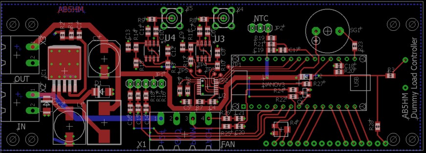
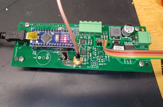
Controller:
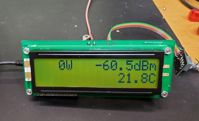
The controller, based on an Arduino NANO, includes signal power measurement with individual calibration for each frequency band, a calorimetric power measurement and the fan speed control.
The signal power measurement is based on a AD8370 Logarithmic Amplifier, connected to a 24bit D/A converter with a measurement range of about 80dB.
The fan speed is controlled by a PWM signal. The duty cycle is based on the flange temperature of the resistors, which can operate up to 100°C without derating.
The calorimetric power measurement is based on the temperature rise of a known thermal mass (our heatsink with heat spreader and resistors) over a defined time. The measurement is slow (10 sec.) and needs to be calibrated to the thermal mass, but is very precise.
And this is the final result:
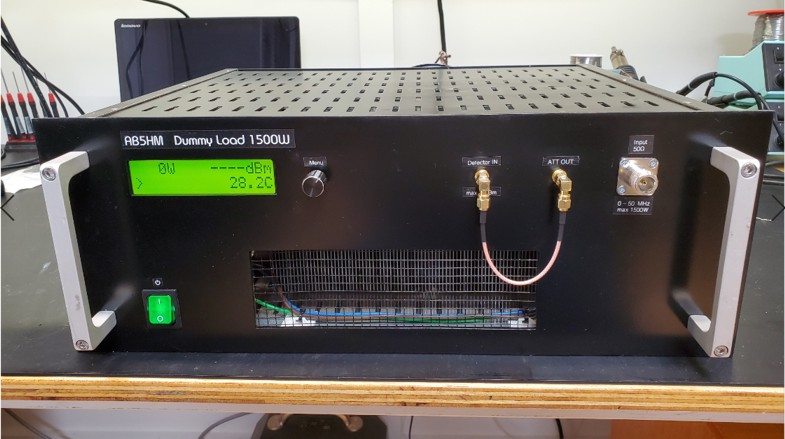
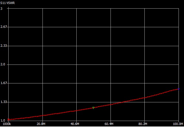
Performance:
1500W continuous at 75F ambient temperature
2000W peak
VSWR (50MHz) : 1.2
VSWR (100MHz) : 1.5