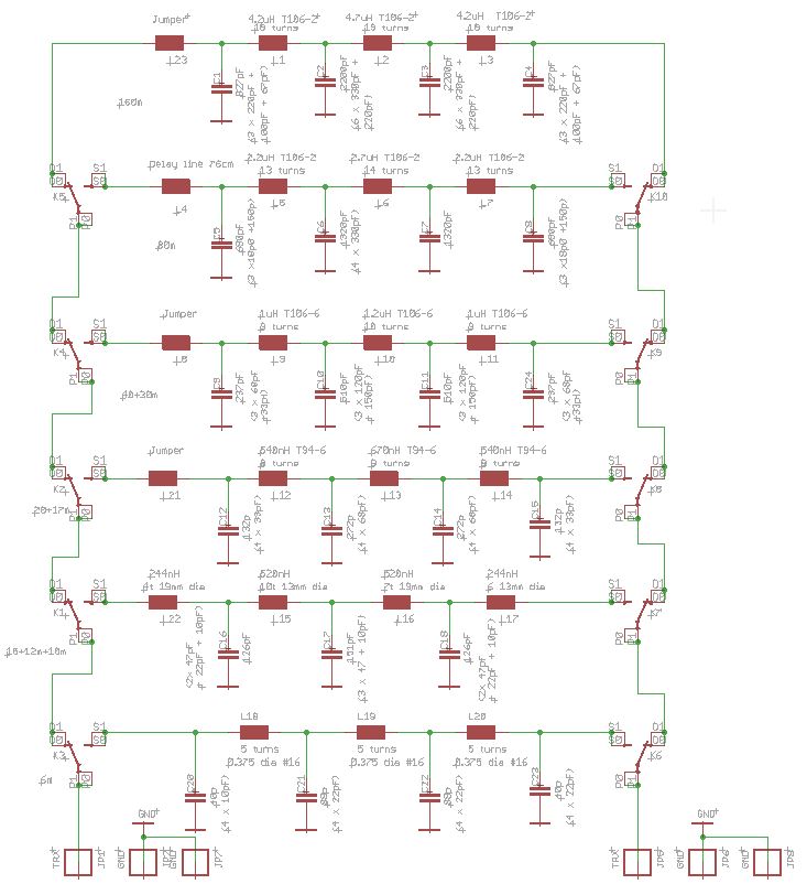
Output lowpass Filter
The output lowpass filter is needed to supress the harmonics, generated by the amplifier.
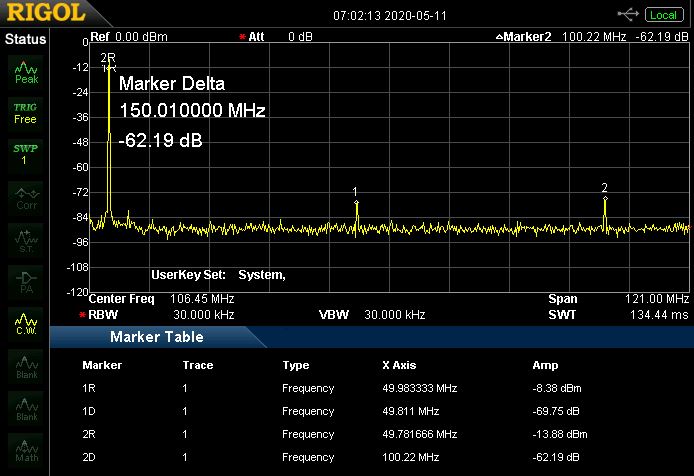
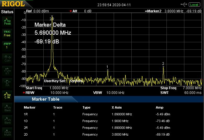
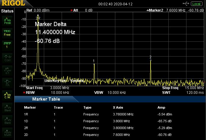
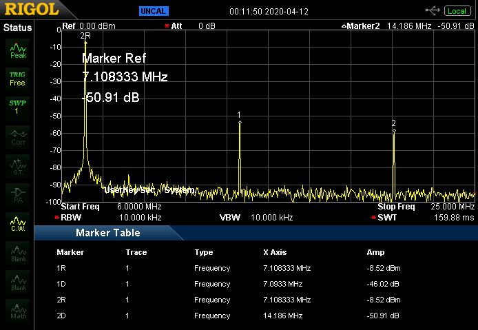
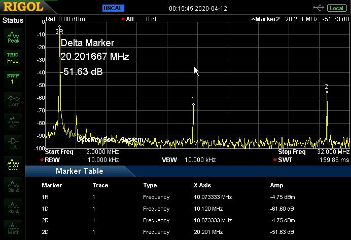
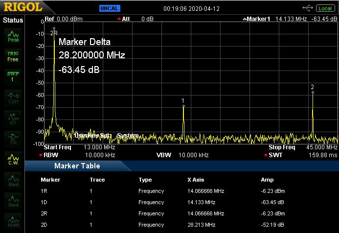
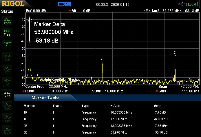
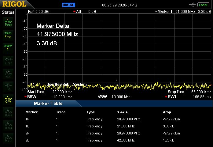
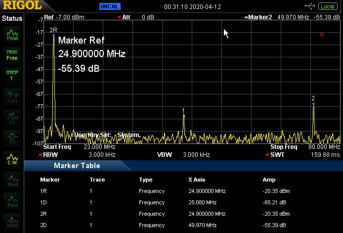
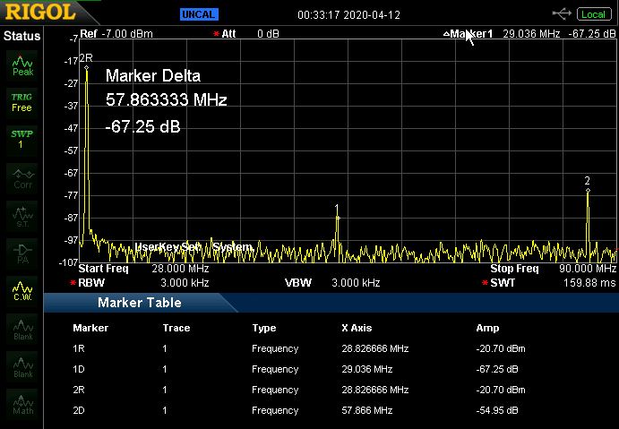
FCC 97.307 requiers the mean power of any spurious emiision on a frequency below 30MHz to be at least 43dB below the mean power of the fundamental emission. For Frequencies between 30-255MHz the limit is 60dB.
I based my filter on the design of Jim (W6PQL). His layout allows multiple different filter configurations.
The main differene is the incorporation of the relay drivers onto this board and air wound inductors for the 17m to 10m section.
As already mentiond in the introduction of this amplifier, the 80m filter section is running a bit hot in long time
CW transmission. However, this is no issue at all in SSB mode. Further experiments and measurements are needed to find the root cause. In the meanwhile i added a temperature sensor and an addtional fan for this section.
Jim also suggested to add a delay line at the input of the 80m section. It definely helped to increase the ouput power in my setup as well.
The filter needs to be tuned in order to minimize losses (heat) and frequency response.
Every 10th of a dB creates already a lot of heat at this power level (at 1500W 0.1dB euquals 34W in heat).
Therefore a vector network analyzer is highly recommended. A cheap miniVNA off Amazon will do just fine.
Tuning the 17m and 10m section is a bit tricky due to resonances in the 17m section that are coming from the 10m
section. The resonance needs to be tuned just to be above the 17m band.

Output Harmonics:
With this filter, the FCC 97.307 requirements are fulfilled.
160m
80m
40m
30m
20m
17m
15m
12m
10m
6m